はじめに
シリアル通信を試しました
注意点
SWIOだけではシリアル通信できません。
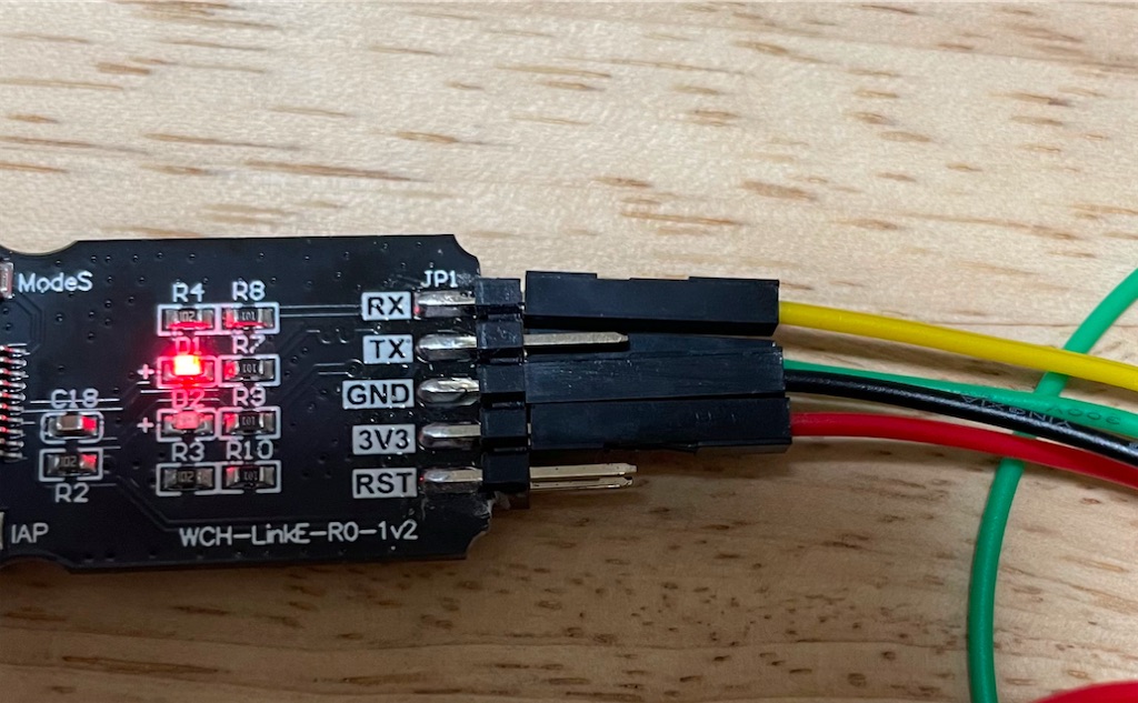
WCH-LinkEのRXとCH32V003F4P6のUTX(pin2,PD5)を接続する必要があります。
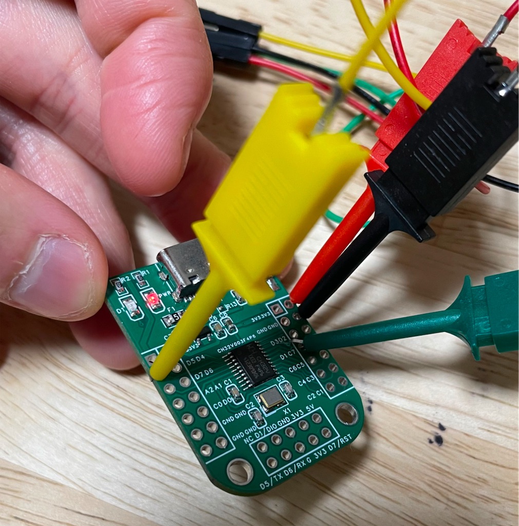
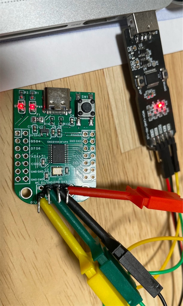
接続
3.3V GND SWIO(PD1) TX(PD5)の4本です。
プログラム
サンプルがほぼそのままで動作しました。楽〜C:\Users\USERNAME\Downloads\ch32v003fun\examples\uart_tx_dma\uart_tx_dma.c
ch32v003funをWindowsに構築しCH32V003F4P6でLチカ | atooshi-noteでch32v003funをダウンロードした場所と同じです。
接続してポートを認識しており(COM7でした)、teratermで通信を確認しました。
/*
 * This example uses DMA for the UART to transfer the "Hello World!\r\n" string
 * once per second. Connect a UART Rx pin to D5, flash the example, setup your
 * uart for 115200n1 and the messages should appear

 シリアル通信のチェック
 */

#include "ch32v003fun.h"

// Set UART baud rate here
#define UART_BR 115200
// LED on D6 (nanoCH32V003 board)
// #define LED_PIN 6
#define LED_PIN 4 // ch32v003f4p6のdevelopmetboard

// DMA transfer completion interrupt. It will fire when the DMA transfer is
// complete. We use it just to blink the LED
__attribute__((interrupt)) __attribute__((section(".srodata")))
void DMA1_Channel4_IRQHandler(void)
{
	// Clear flag
	DMA1->INTFCR |= DMA_CTCIF4;

	// Blink LED
	GPIOD->OUTDR ^= 1<<LED_PIN;
}

static void led_setup(void)
{
	RCC->APB2PCENR = RCC_APB2Periph_GPIOD;
	GPIOD->CFGLR =
		((GPIO_CNF_IN_PUPD)<<(4*1)) | // Keep SWIO enabled.
		(GPIO_Speed_2MHz | GPIO_CNF_OUT_PP)<<(4*LED_PIN);

	// LED ON
	GPIOD->BSHR = 1<<LED_PIN;
}

static void uart_setup(void)
{
	// Enable UART and GPIOD
	RCC->APB2PCENR |= RCC_APB2Periph_GPIOD | RCC_APB2Periph_USART1;

	// Push-Pull, 10MHz Output on D5, with AutoFunction
	GPIOD->CFGLR = (GPIOD->CFGLR & ~(0xF<<(4*5))) |
			((GPIO_Speed_10MHz | GPIO_CNF_OUT_PP_AF)<<(4*5));

	// Setup UART for Tx 8n1
	USART1->CTLR1 = USART_WordLength_8b | USART_Parity_No | USART_Mode_Tx;
	USART1->CTLR2 = USART_StopBits_1;
	// Enable Tx DMA event
	USART1->CTLR3 = USART_DMAReq_Tx;

	// Set baud rate and enable UART
	USART1->BRR = ((FUNCONF_SYSTEM_CORE_CLOCK) + (UART_BR)/2) / (UART_BR);
	USART1->CTLR1 |= CTLR1_UE_Set;
}

static void dma_uart_setup(void)
{
	// Enable DMA peripheral
	RCC->AHBPCENR = RCC_AHBPeriph_SRAM | RCC_AHBPeriph_DMA1;

	// Disable channel just in case there is a transfer in progress
	DMA1_Channel4->CFGR &= ~DMA_CFGR1_EN;

	// USART1 TX uses DMA channel 4
	DMA1_Channel4->PADDR = (uint32_t)&USART1->DATAR;
	// MEM2MEM: 0 (memory to peripheral)
	// PL: 0 (low priority since UART is a relatively slow peripheral)
	// MSIZE/PSIZE: 0 (8-bit)
	// MINC: 1 (increase memory address)
	// CIRC: 0 (one shot)
	// DIR: 1 (read from memory)
	// TEIE: 0 (no tx error interrupt)
	// HTIE: 0 (no half tx interrupt)
	// TCIE: 1 (transmission complete interrupt enable)
	// EN: 0 (do not enable DMA yet)
	DMA1_Channel4->CFGR = DMA_CFGR1_MINC | DMA_CFGR1_DIR | DMA_CFGR1_TCIE;

	// Enable channel 4 interrupts
	NVIC_EnableIRQ(DMA1_Channel4_IRQn);
}

static void dma_uart_tx(const void *data, uint32_t len)
{
	// Disable DMA channel (just in case a transfer is pending)
	DMA1_Channel4->CFGR &= ~DMA_CFGR1_EN;
	// Set transfer length and source address
	DMA1_Channel4->CNTR = len;
	DMA1_Channel4->MADDR = (uint32_t)data;
	// Enable DMA channel to start the transfer
	DMA1_Channel4->CFGR |= DMA_CFGR1_EN;
}

int main(void)
{
	static const char message[] = "Hello World!!!\r\n";

	SystemInit();
	led_setup();
	uart_setup();
	dma_uart_setup();

	while (1)
	{
		dma_uart_tx(message, sizeof(message) - 1);
		Delay_Ms(1000);
	}
}
参考
CH32V003をArduinoで使う: DJ HIGO オフィシャルブログ
以上:)